An RF sensing device is required for two purposes:
- to measure the amount of incoming and reflected power for the purpose of system health check and PA protection.
- to detect the change from Rx to Tx by sensing the incoming signal from the transceiver to the PA. This signal will trigger the sequencer and change the configuration accordingly.
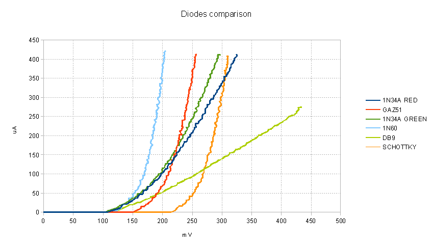
The circuit I plan to use is derived from the one of W6PQL. However, for the RF sensing I want to use the most sensible circuit since early detection of incoming RF is critical for the protection of the LNA. Therefore I have investigated the characteristics of a bunch of germanium diodes compared with the ones of a hot carrier diode with very low forward voltage drop.

I checked:
- a couple of 1N34A, one Panasonic with red band and another one with green band
- one Tesla GAZ51
- one russian DB9
- one 1N60
- one Schottky SD101C from Vishay Semiconductor
Clearly, for small signal, the Schottky diode I tested cannot compete with 1N60. However, performance at the target frequency (432 MHz) will have to be checked before drawing conclusions in my case.
The curves have been traced from measurements taken with an Arduino Mega.
For the ones interested here is the code:
/* Diode Curve Generator for Seeeduino Mega (or any Arduino Mega)
The PWM output in port 3 (Timer 3) is used as a DAC to drive a RC
filter 10kohms-0.1uF.
The DAC voltage is applied to the diode that goes to ground via a
resistor of about 1 kOhm. Voltages at anode and catode (that is
the voltage over the resistor) are measured via A1 and A2.
Control and output via Serial Monitor. Data collection starts
sending any character. Values, tab separated, can be copied into a
spreadsheet.
June 29th, 2013 by CE3TDK
*/
#include <TimerOne.h>
#include <TimerThree.h>
const byte PWMDAC1pin = 3; // PWM DAC in MEGA
const byte PWMDAC2pin = 10; // example using second DAC
const byte period = 32; // for 8 bit DAC
int sensorPin = A0; // select the input pin
int sensorPin1 = A1; // select the current input pin
int sensorValue = 0; // variable to store the value coming from the sensor
long value,voltage,value2,voltage2,voltagediode,current;
void setup(void)
{ pinMode(PWMDAC1pin, OUTPUT);
Timer3.initialize(period);
// initialize the serial communications:
Serial.begin(57600);
}
void loop(void)
{
while (Serial.available() == 0){
delay(50);}
int inByte = Serial.read();
for(int i=0; i<128; i++)
{ int j = i*8;
Timer3.pwm(PWMDAC1pin, j); // create a sawtooth
delay(50); // settle time 2.3 ms
value = 0;
value2 = 0;
for (int c=0; c<100; c++){ // avrg of 100 readings
// read the value from the sensor:
sensorValue = analogRead(sensorPin);
// print the sensor values:
value += sensorValue;
sensorValue = analogRead(sensorPin1);
// print the sensor values:
value2 += sensorValue;
delay(1);
}
voltage = (value * 50 )/1024; // 5000 mv divided 100 reading => 50
voltage2 = (value2 * 50 )/1024; // 5000 mv divided 100 reading => 50
voltagediode = voltage - voltage2; // voltage across diode in mV
current = (voltage2*1000)/992; // r=992 ohm; I in uA
Serial.print(voltagediode);
// print a tab between values:
Serial.print("\t");
// Serial.print(", ");
Serial.print(current);
Serial.println();
}
while (Serial.available() == 0){
delay(50);}
inByte = Serial.read();
}
